
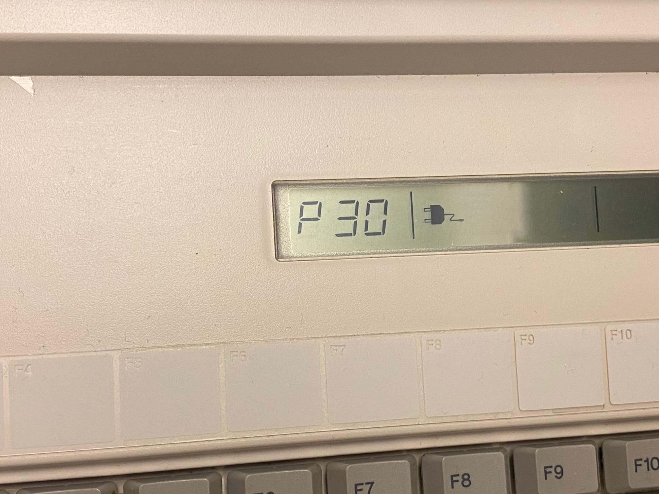
My T4600 didn’t boot any more and just showed a P30 error on the small LCD.
Fortunately this seems to be a known problem: a capacitor died and has to be replaced.
But getting this thing apart and back together is a god damn jigsaw puzzle. I took it apart twice and both times I ended up a few screws too many…
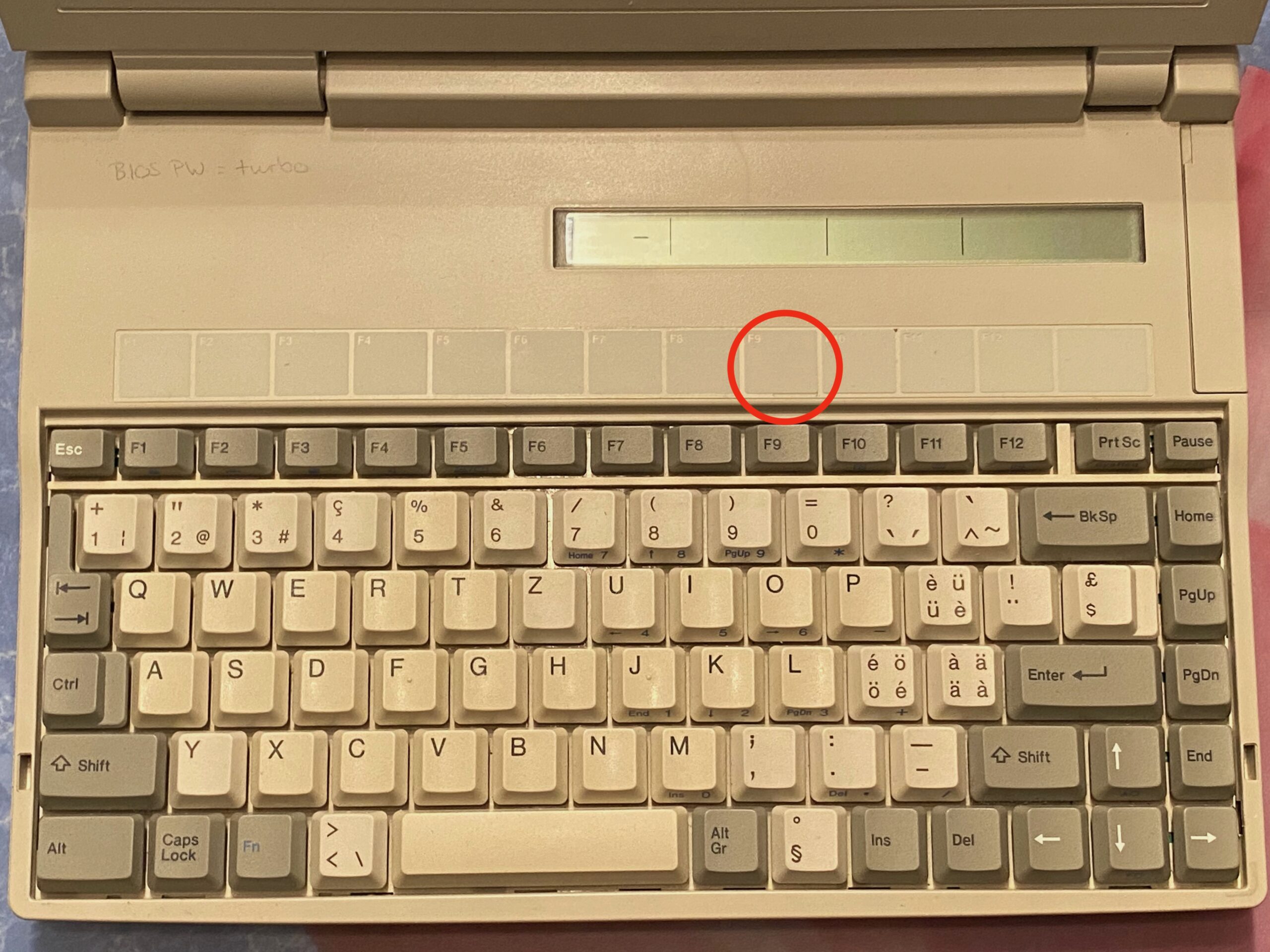
- 1. Let’s start with the hidden screws. The first one is right above the F9 key, under the function key label.
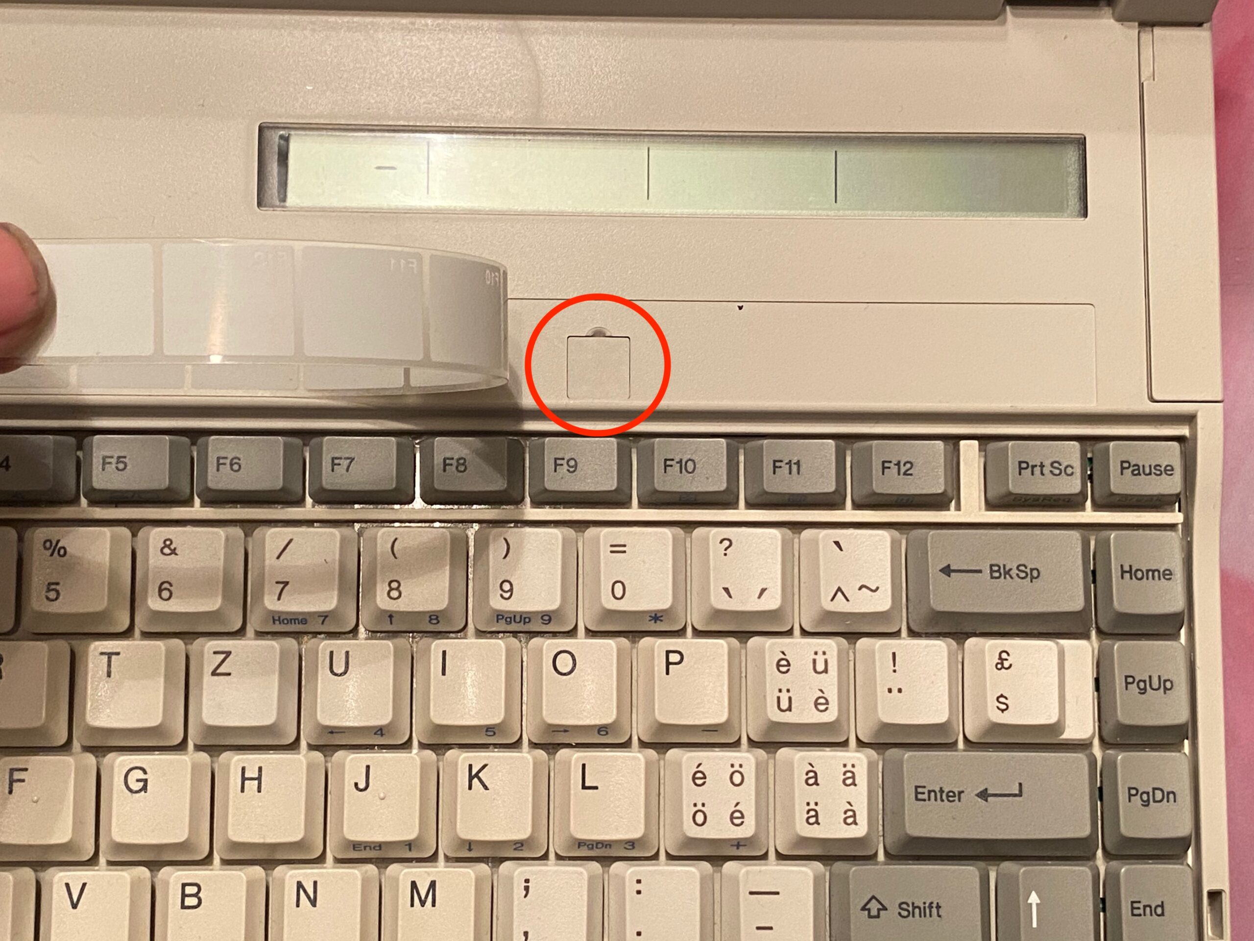
- 2. Peel back the label and open the small cover.
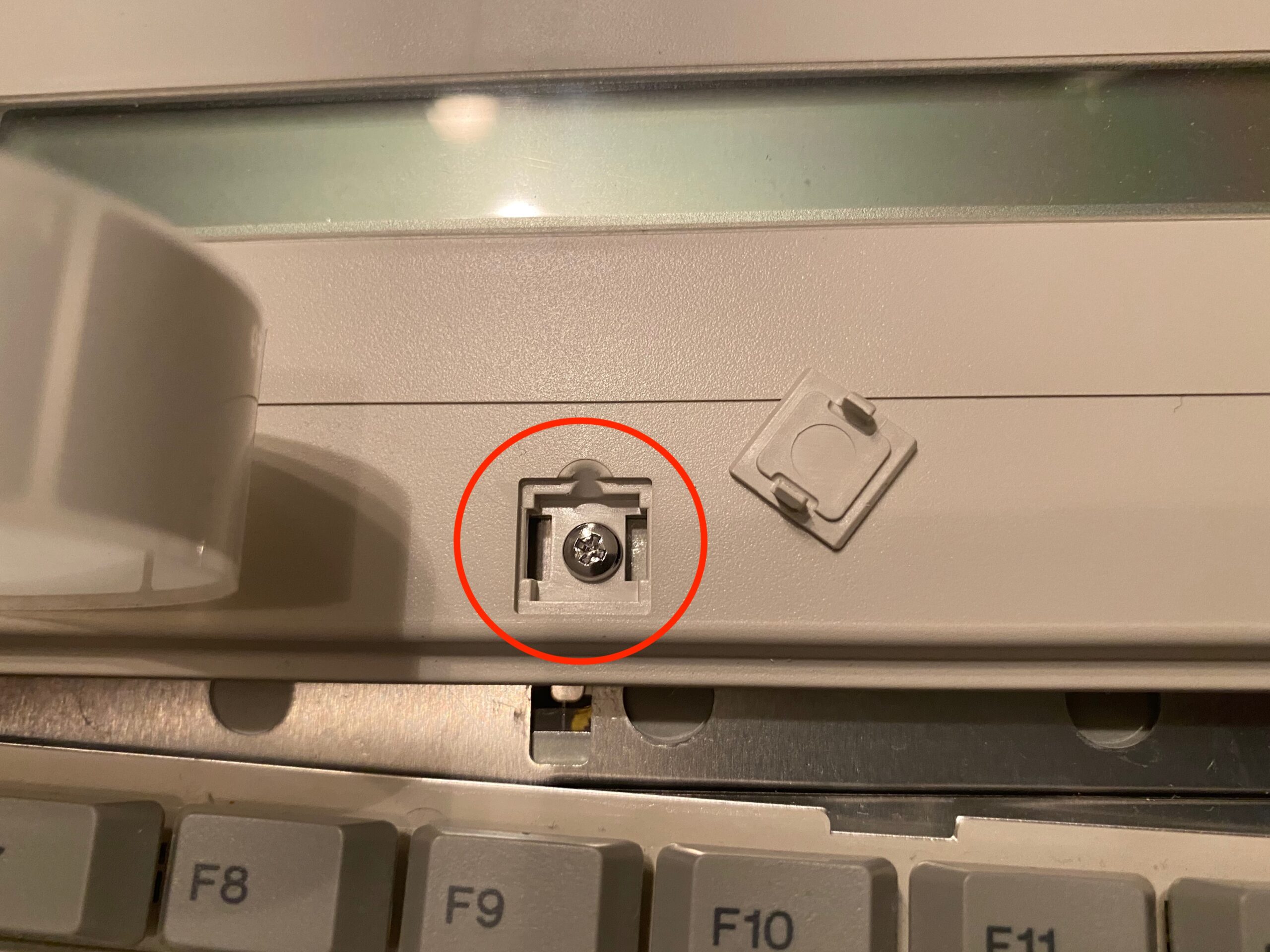
- 3. There is our first screw.
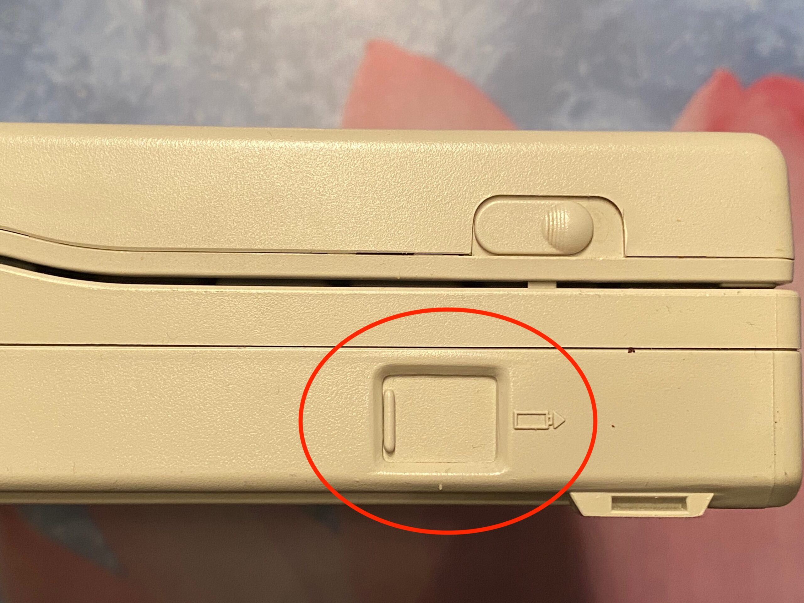
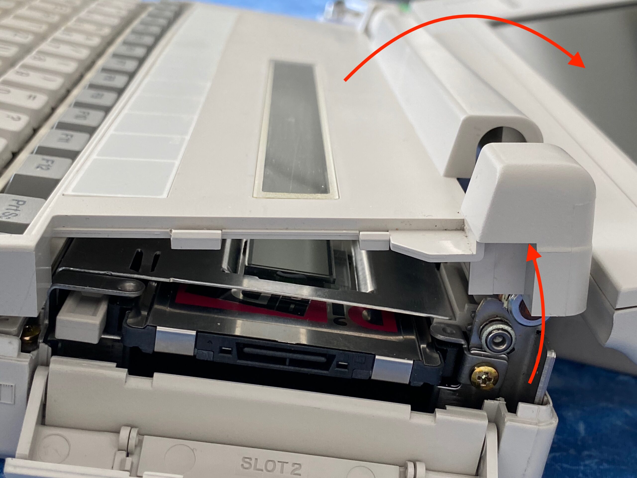
- 4. Now we need to remove the battery. On the left side of the laptop, slide the cover towards you.
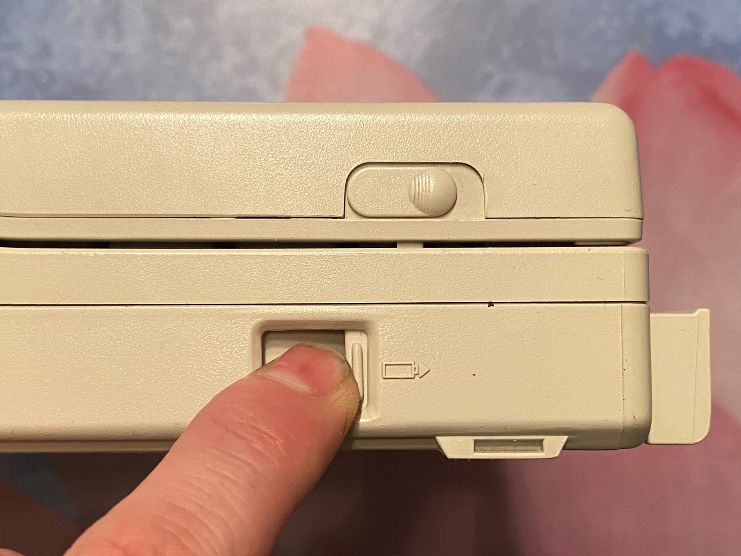
- 5. Press the button underneath and the battery will pop out. Take it out completely.

- 6. Turn the laptop upside down and look into the battery compartment. There’s our second hidden screw.
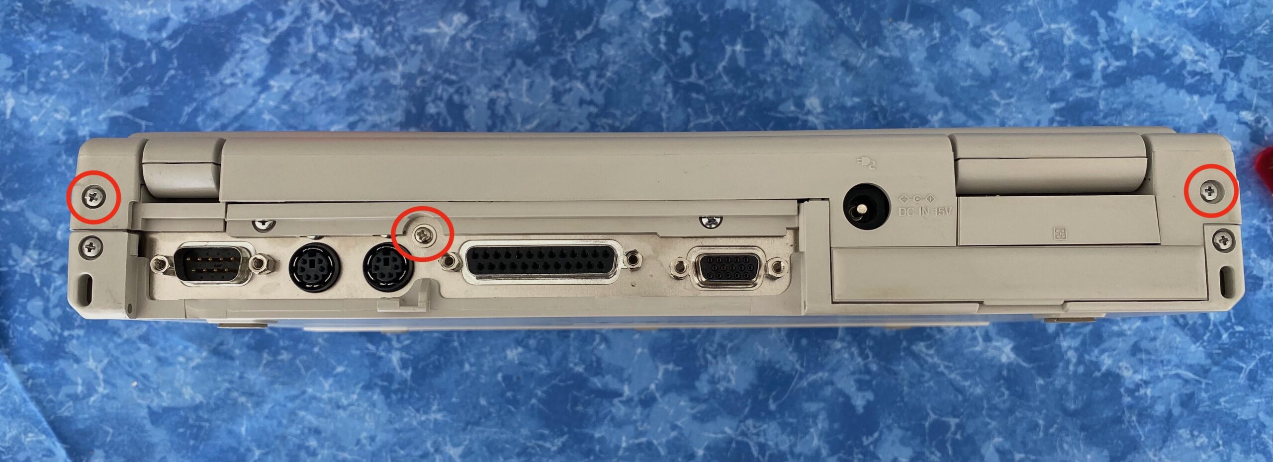
- 7. Now we go to the back and remove those three screws.
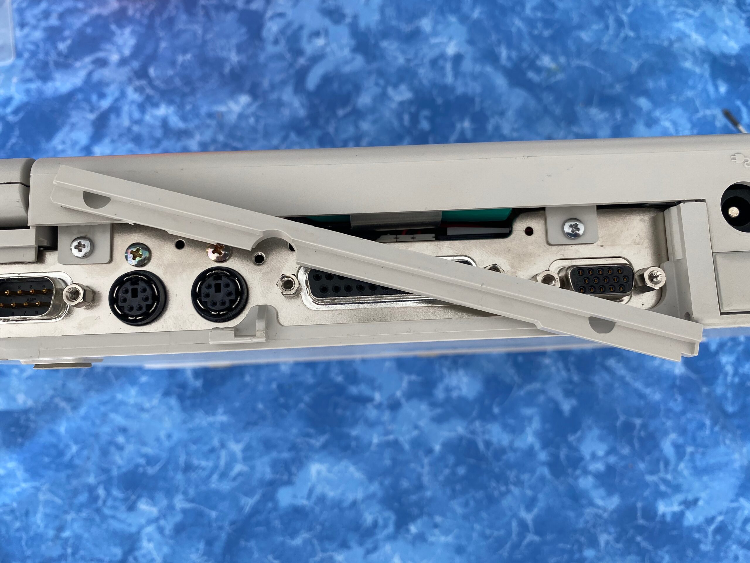
- 8. Remove this plastic part. It’s just there to hide the next two screws.
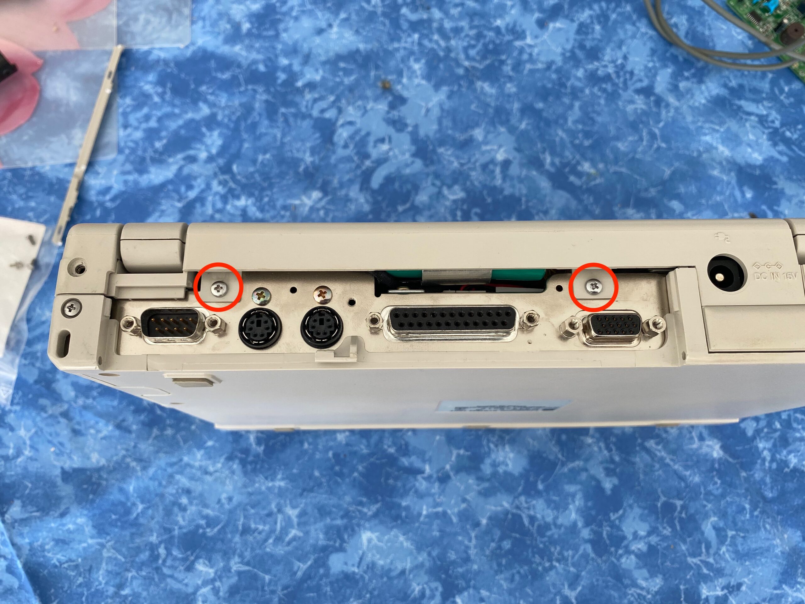
- 9. Remove those two screws.
- 10. Push down the display lid until it’s almost flat. Then gently pull up the top part of the plastic case. It should be loose.

- 11. Pull up on both sides of the case.
- 12. Now work your way to the front and wiggle the plastic frame loose. There are no more screws, but it holds pretty firmly. You may need some force, but try not to break it.
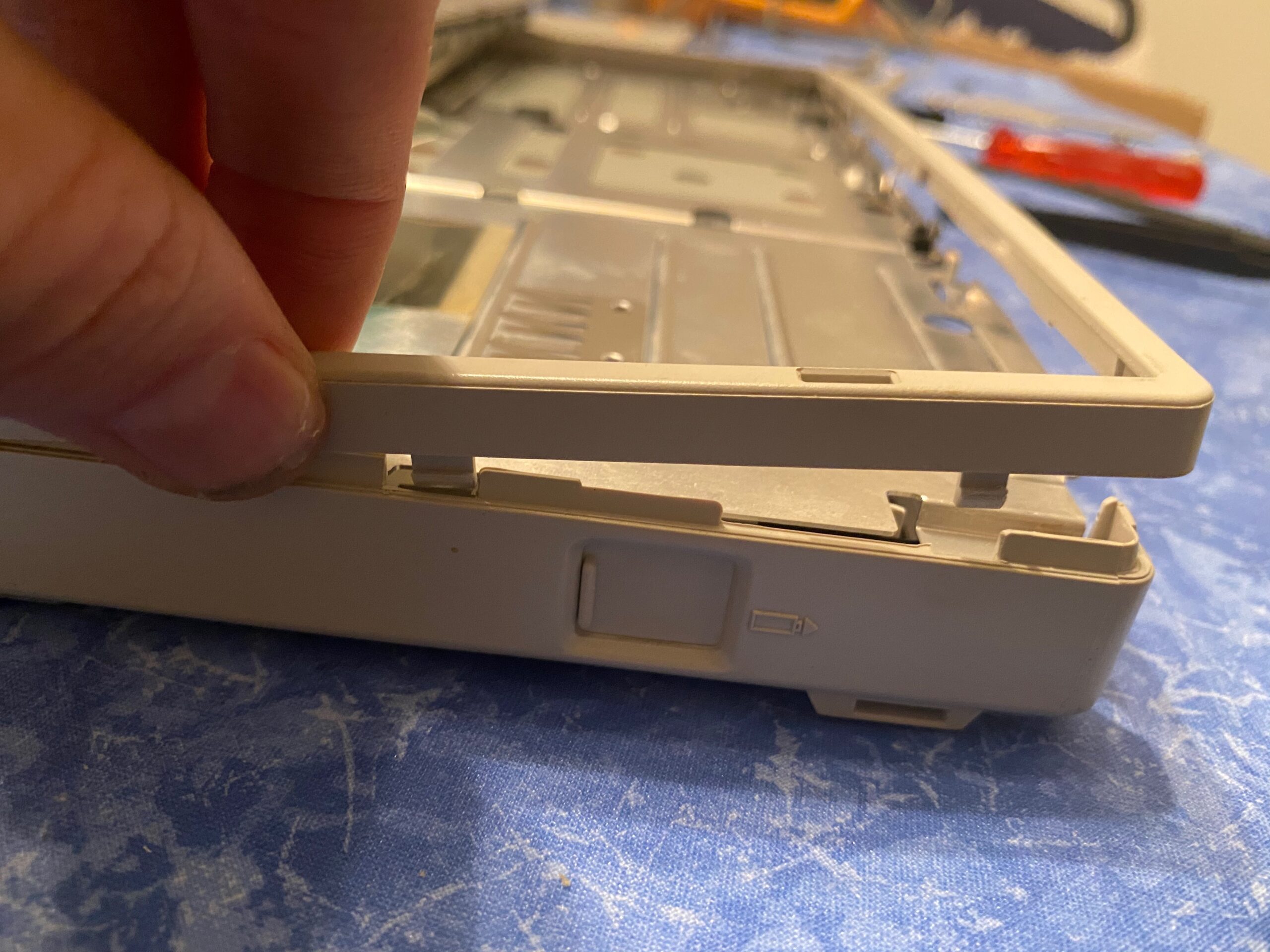
- 13. This may help a bit. You can see the latches where it’s connected.
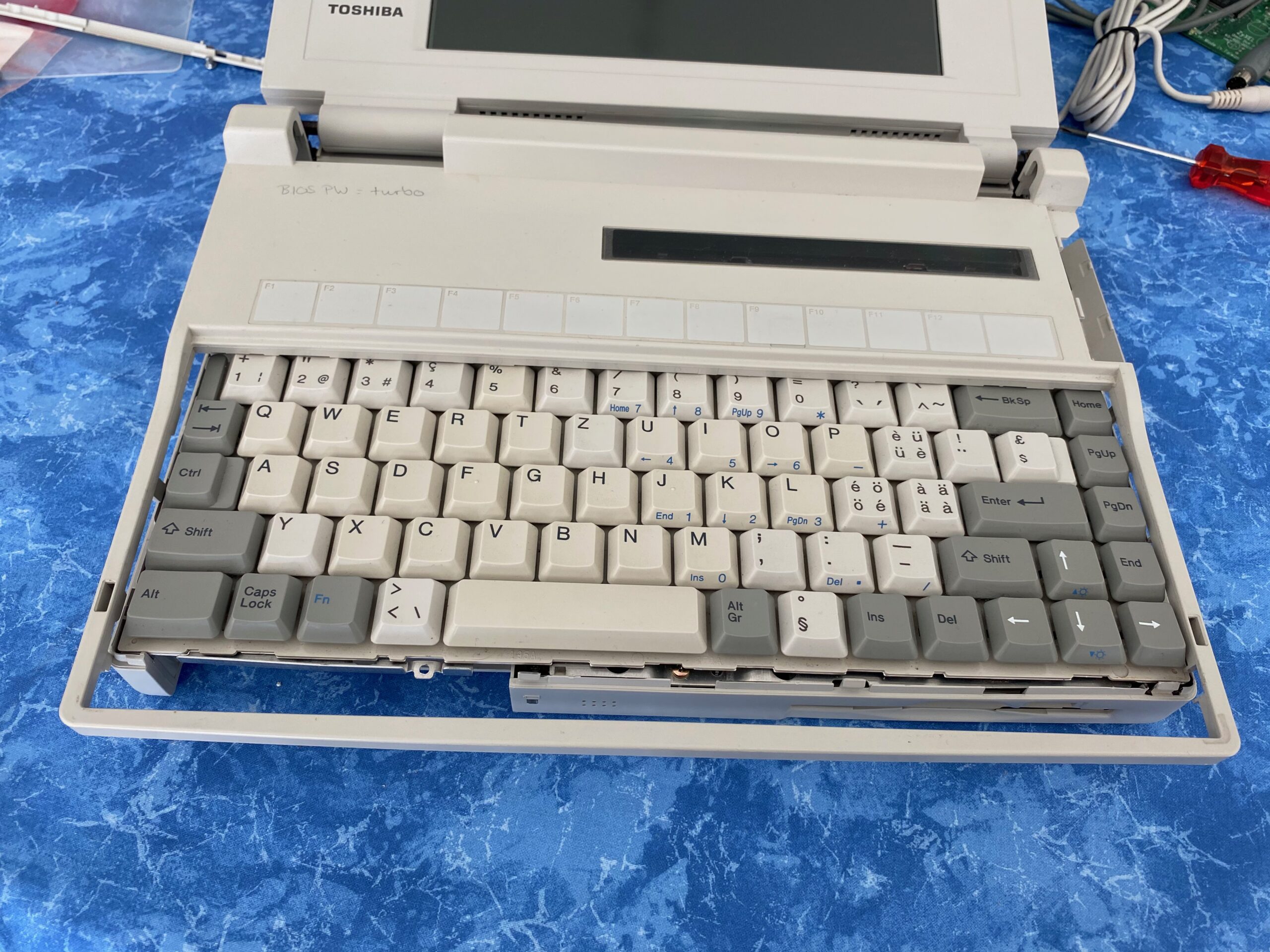
- 14. Lift the keyboard and detach its ribbon cable. Gently pull the small tabs right and left of the brown connector and the cable will be released.
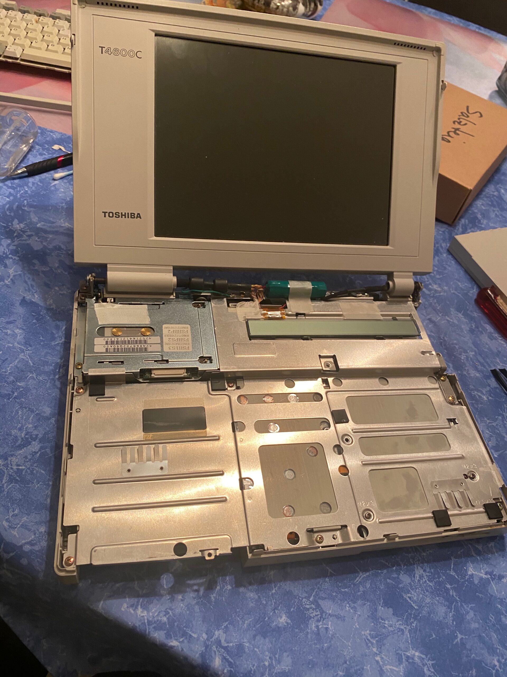
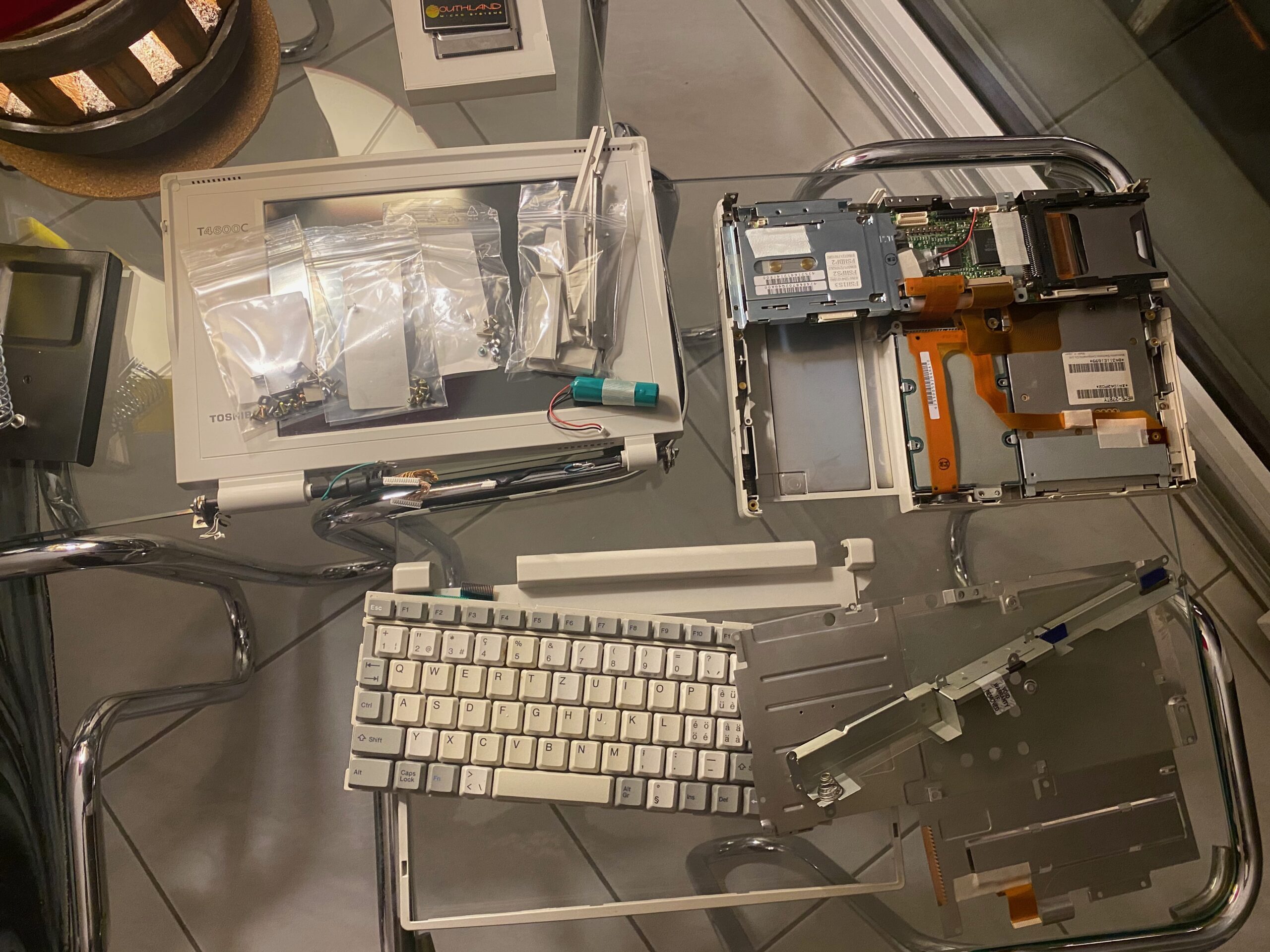
- Your Toshiba should now look like this. That was the easy part, now let’s get at it.
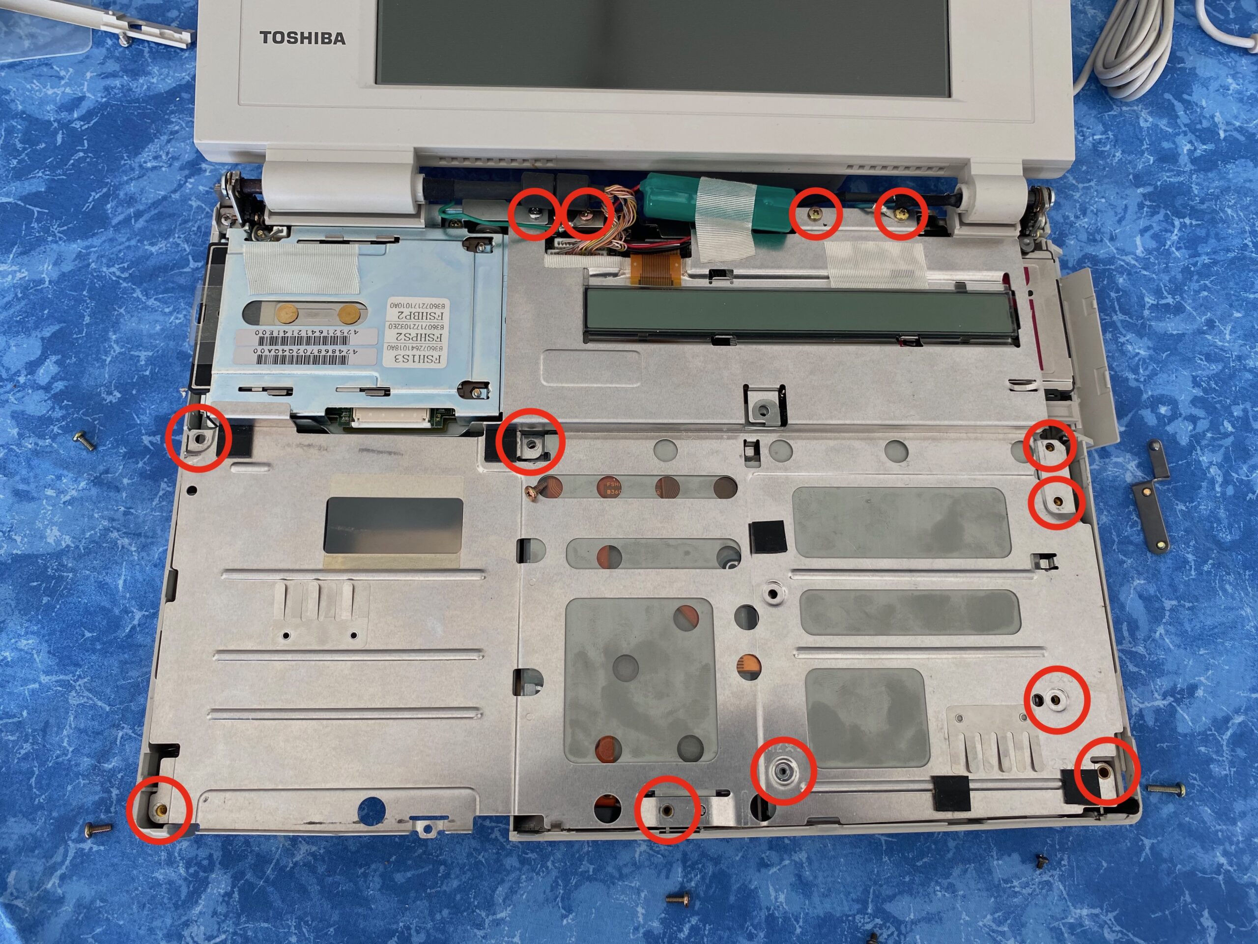
- 15. To get further into the machine, we need to remove those cursed 13 screws to remove the metal sheet. Pay attention to the small LCD! Flip it over to the top to get it out of the way. It’s ribbon cable is very delicate!
The two screws on the right will release a metal bracket.
- At this stage you will have access to the floppy and harddisk by removing some obvious screws.
As we want to fix the P30 error, we have to go down deeper. Down the rabbit hole to the PSU!
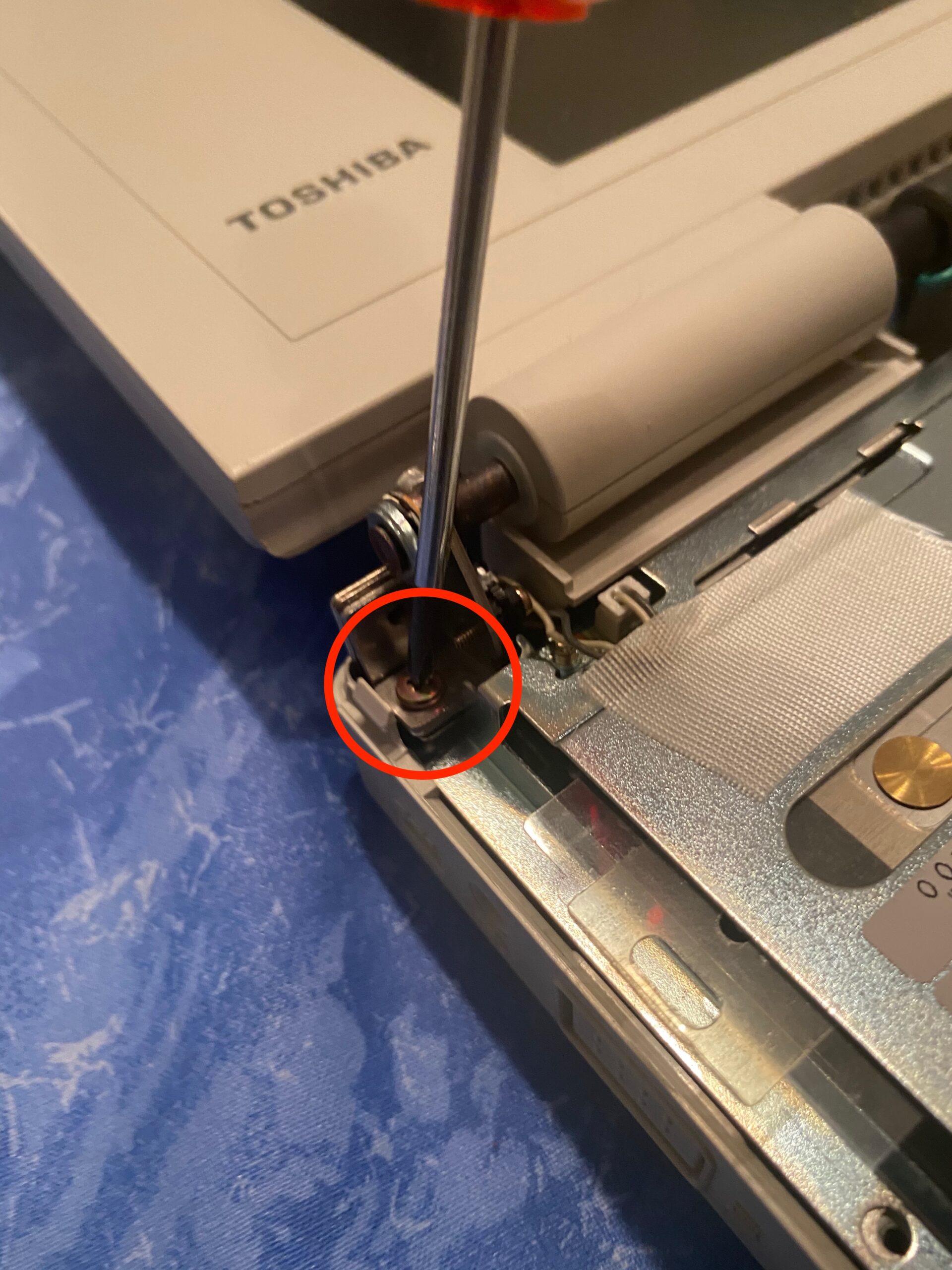
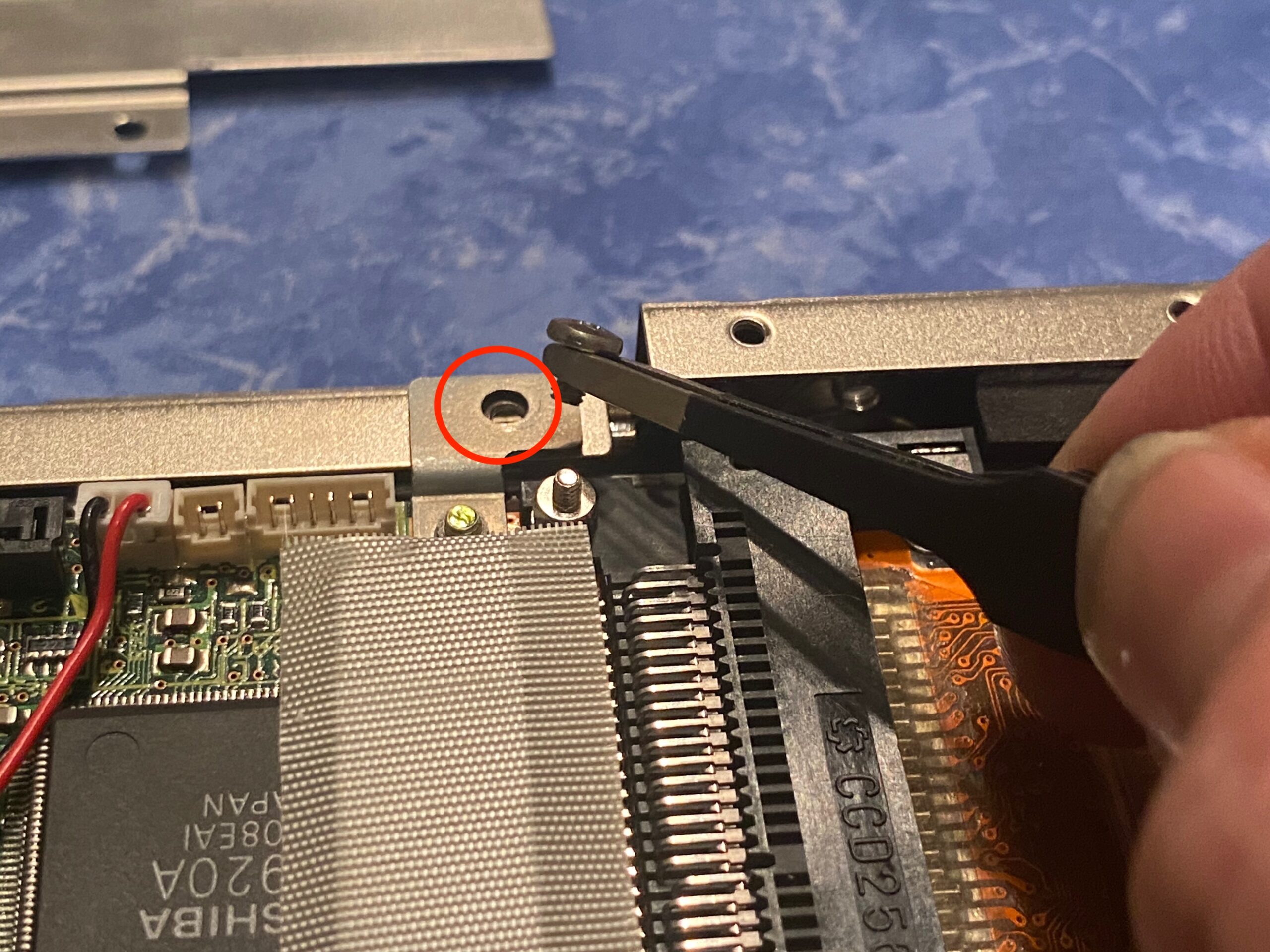
- 16. One more screw on the top left beneath the display hinge.
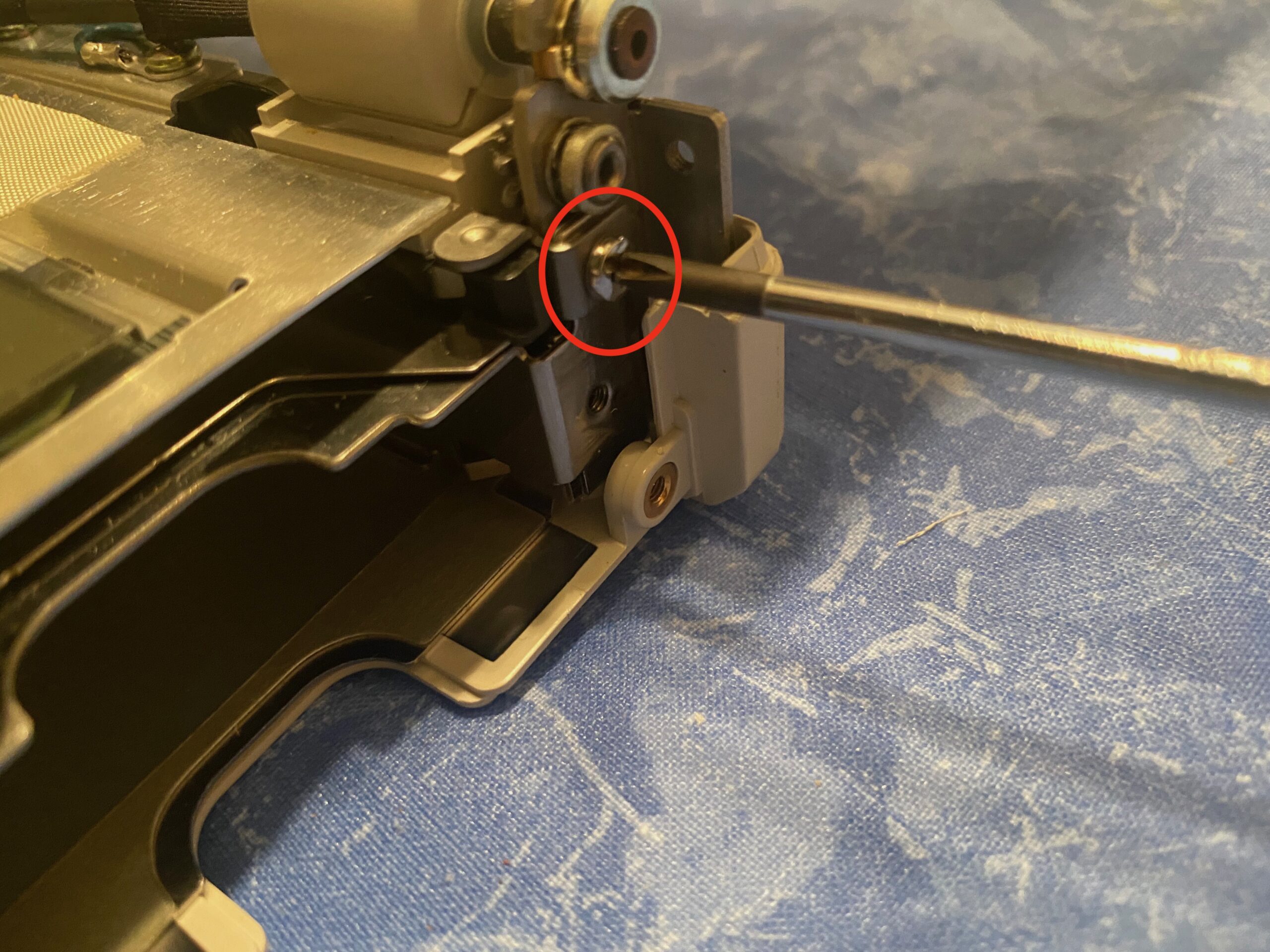
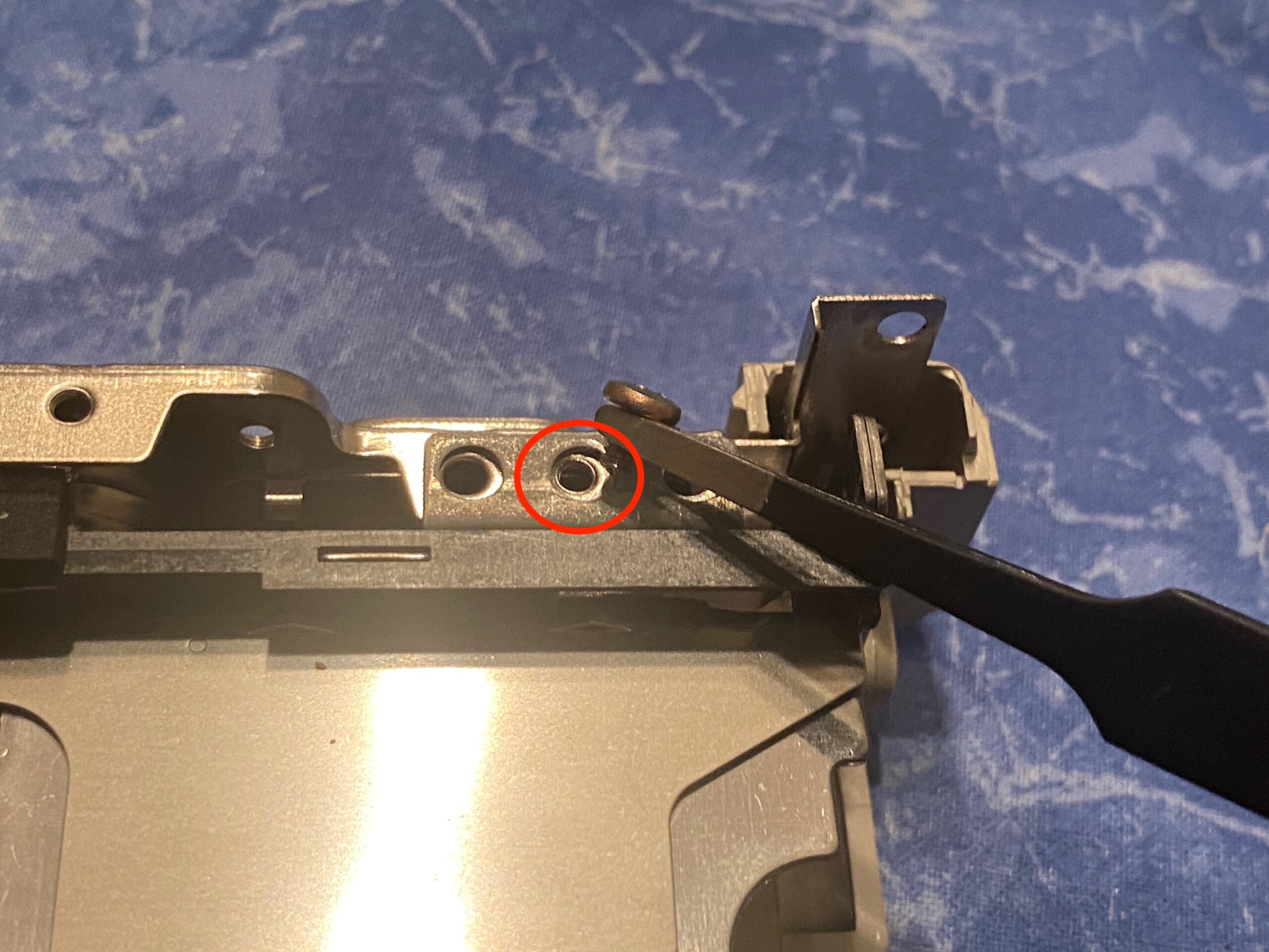
- 17. Similar on the right hand side. The small metal bracket will fall of. Try to remember which way to put it back in.
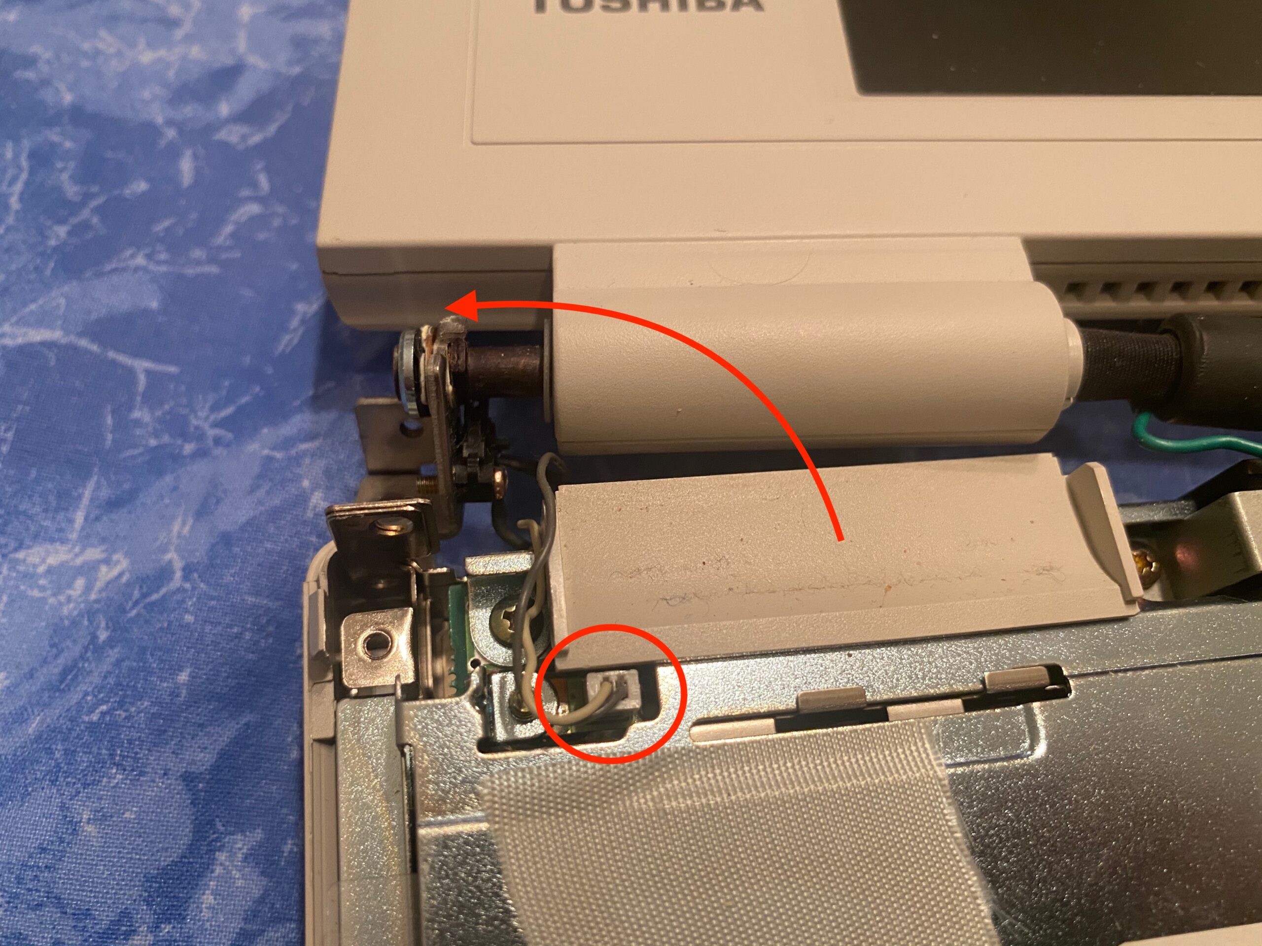
- 18. You can now move the display a little bit to remove the plastic underneath it. Then unplug the small cable.

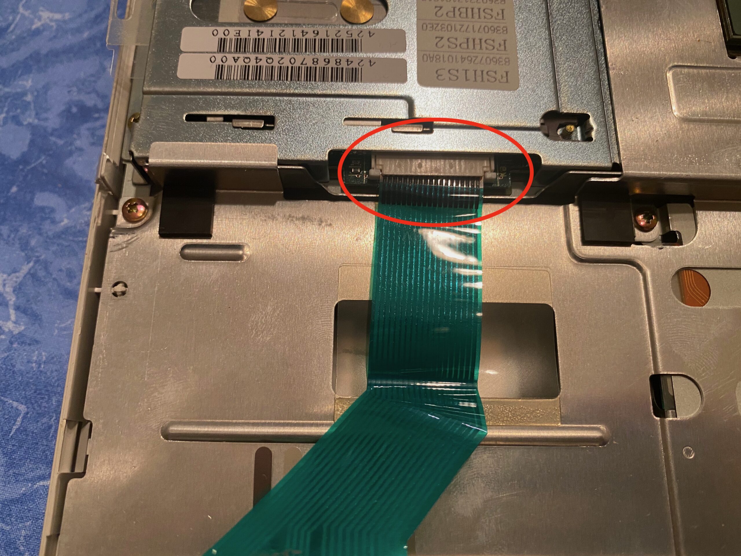
- 19. Disconnect all the cables to the display. There are four:
– two cables with white plugs. Gently pull them up
– one ribbon cable. pull the small tabs right and left and it should lift. then pull the ribbon cable.
– there’s a smaller white plug on the right, this one should be easy.
I left the batteries connected to not lose the CMOS data.
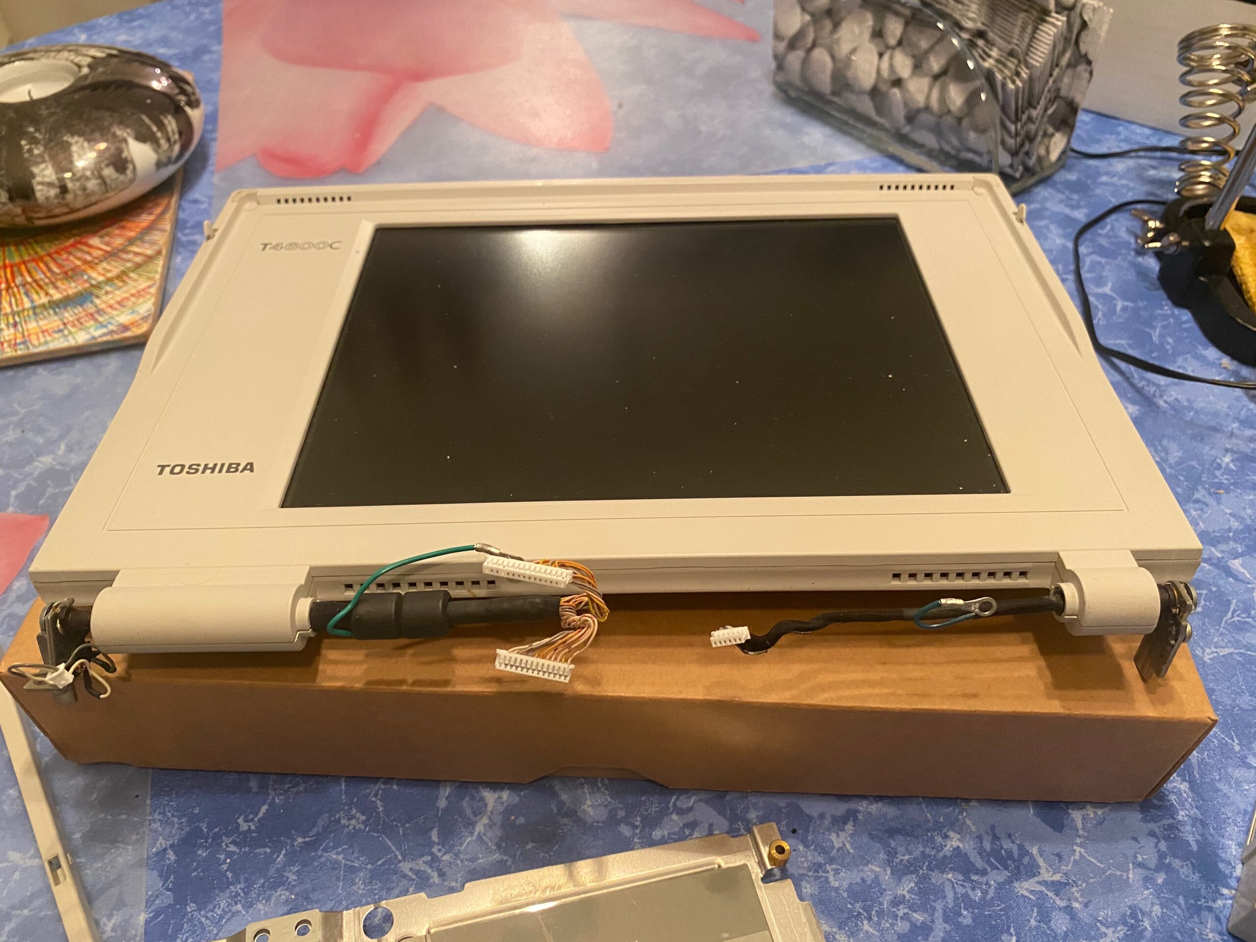
- 20. You should be able to completely remove the display now.
But we’re not finished yet!
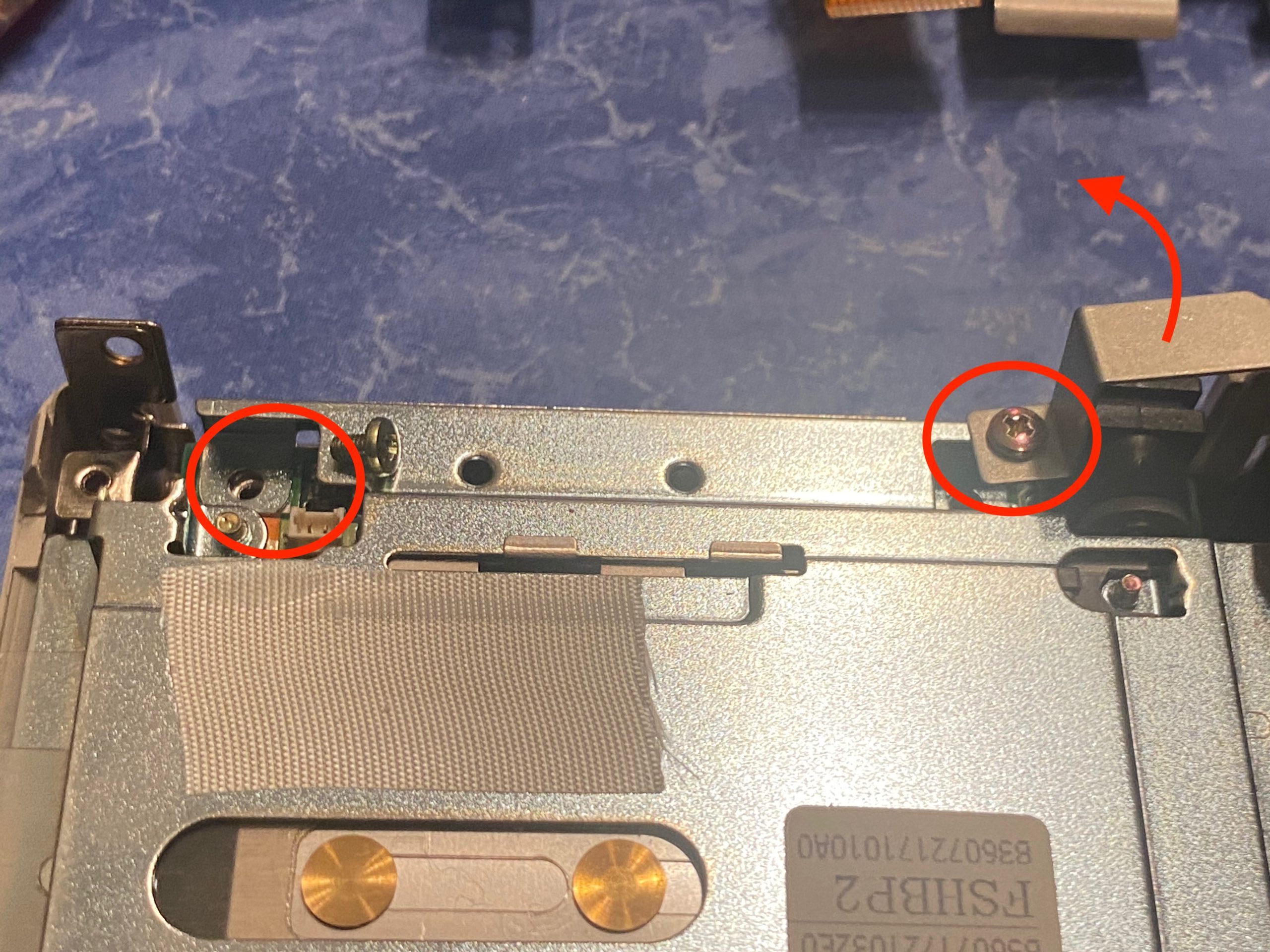
- 21. With the display removed you get access to this screws.
- The right screw will release a metal bracket, keep it safe and don’t lose it.
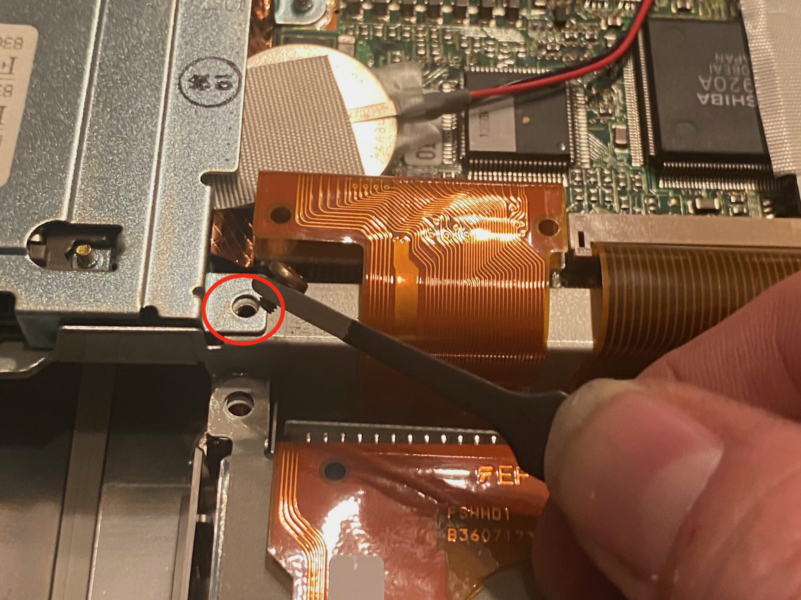
- 22. And this one…
- 23. … and this one, too.
- 24. This is kind of in the centre.
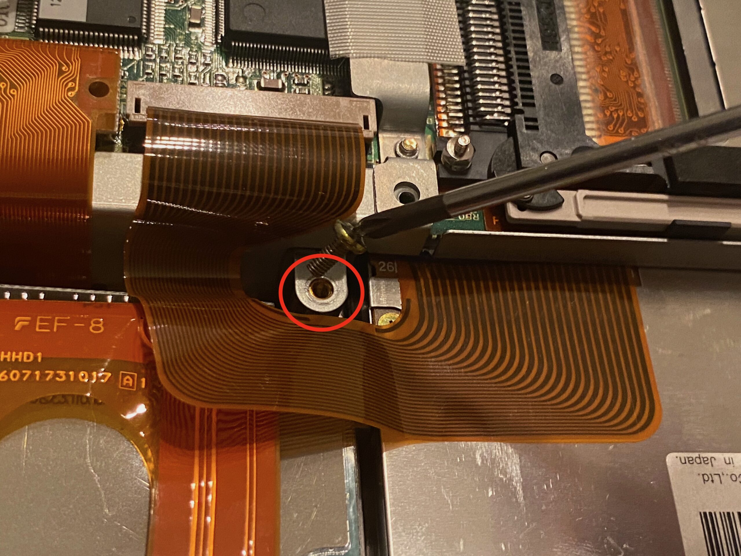
- 25. This is a little further down. The ribbon cable around this screw is the floppy connector, btw.
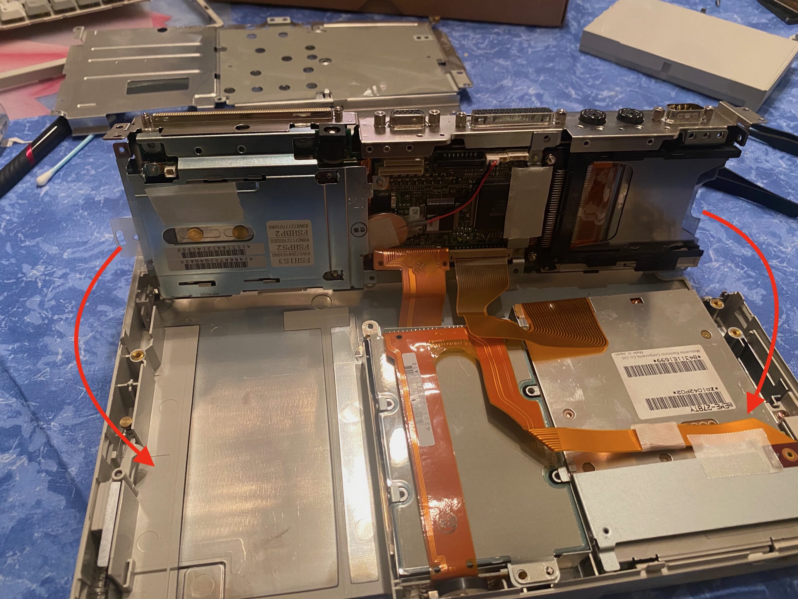
- 26. Now this is an interesting stage. With all the screws removed, you can lift up the whole package. we have to work on the underside of this. So flip it over towards you to reveal its underbelly.

- 27. If you did it right, you should see those three screws. Remove them, too.
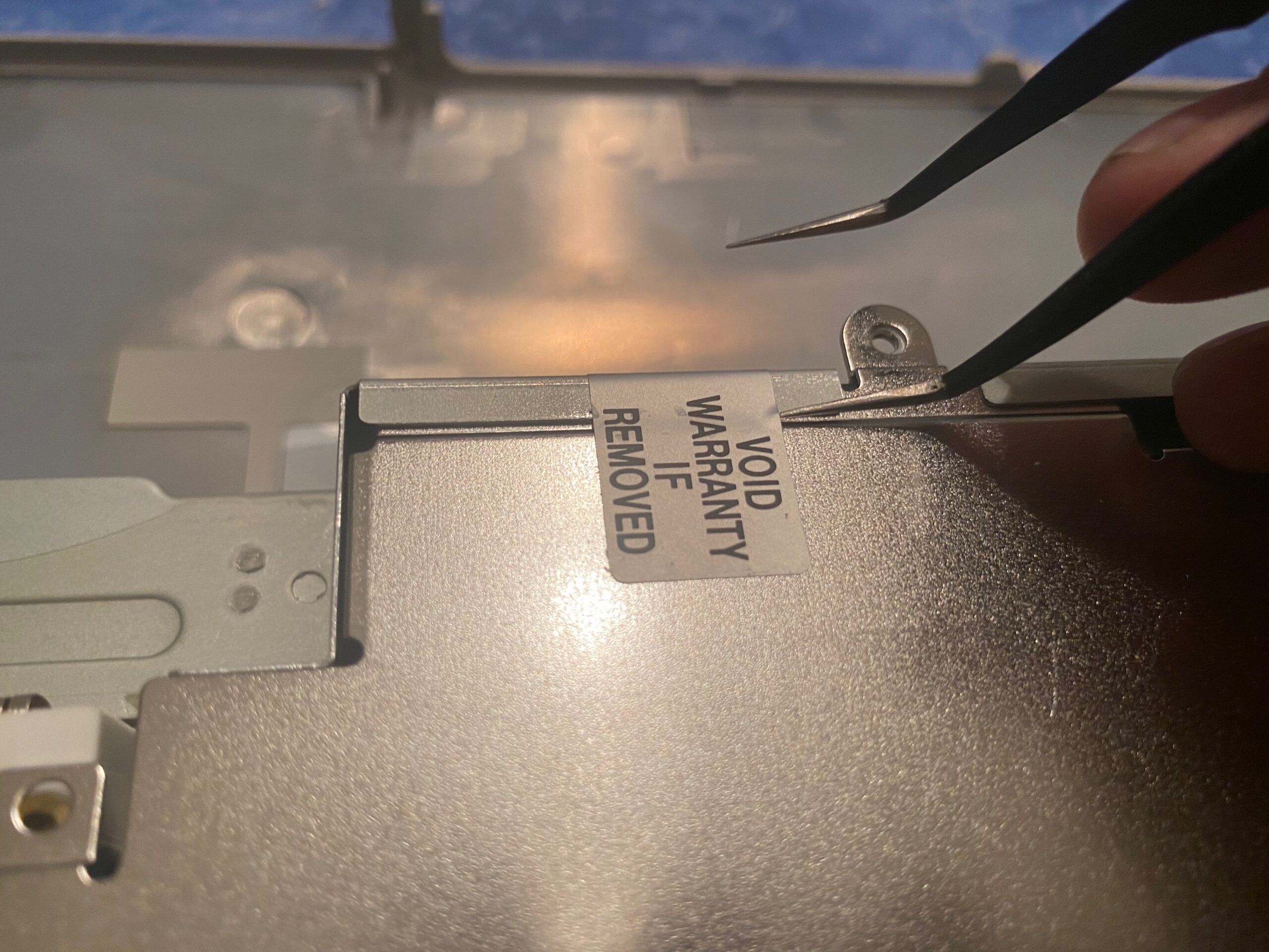
- I think we are way past this point of caring about the warranty…
- 28. But wait, there’s more!
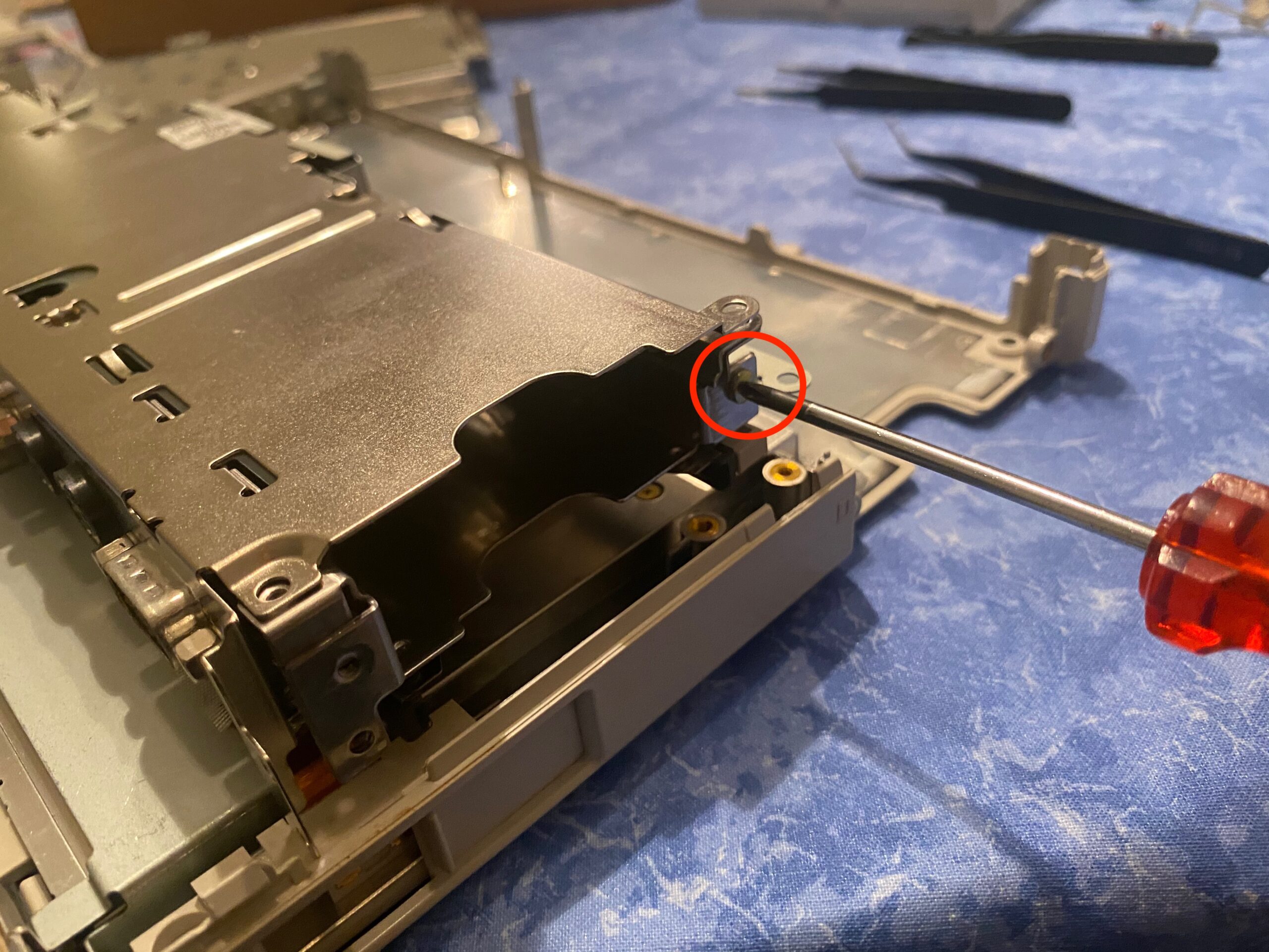
On the right hand side…
- 29. Remove the metal bracket thingy like so.
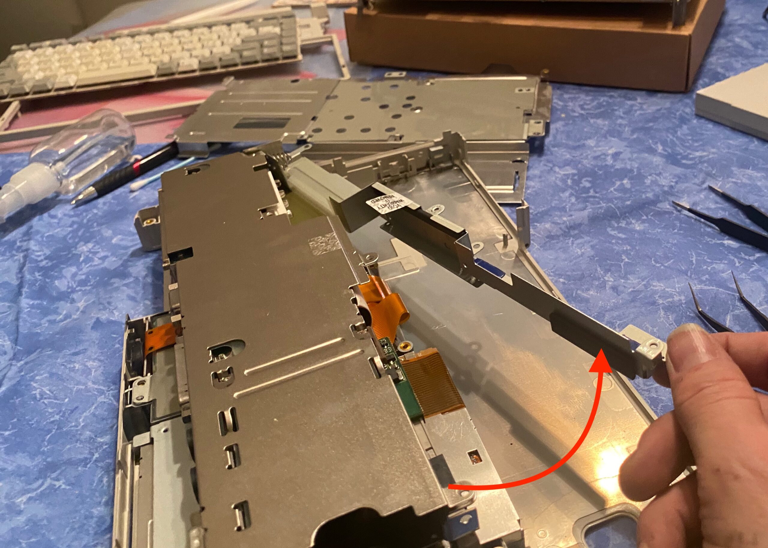
- We’re getting close!
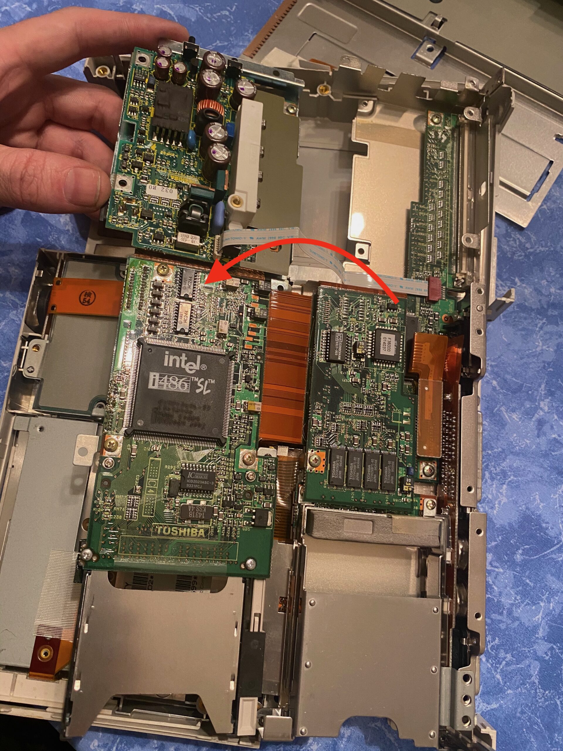
- 30. Now you should be able to open the mainboard sandwich like a book.
- On the top left of this picture you can see the PSU we want to get to!

- 31. Disconnect the small white ribbon cable.
- There we can see our faulty capacitor! But we need to get this board off for the soldering part.
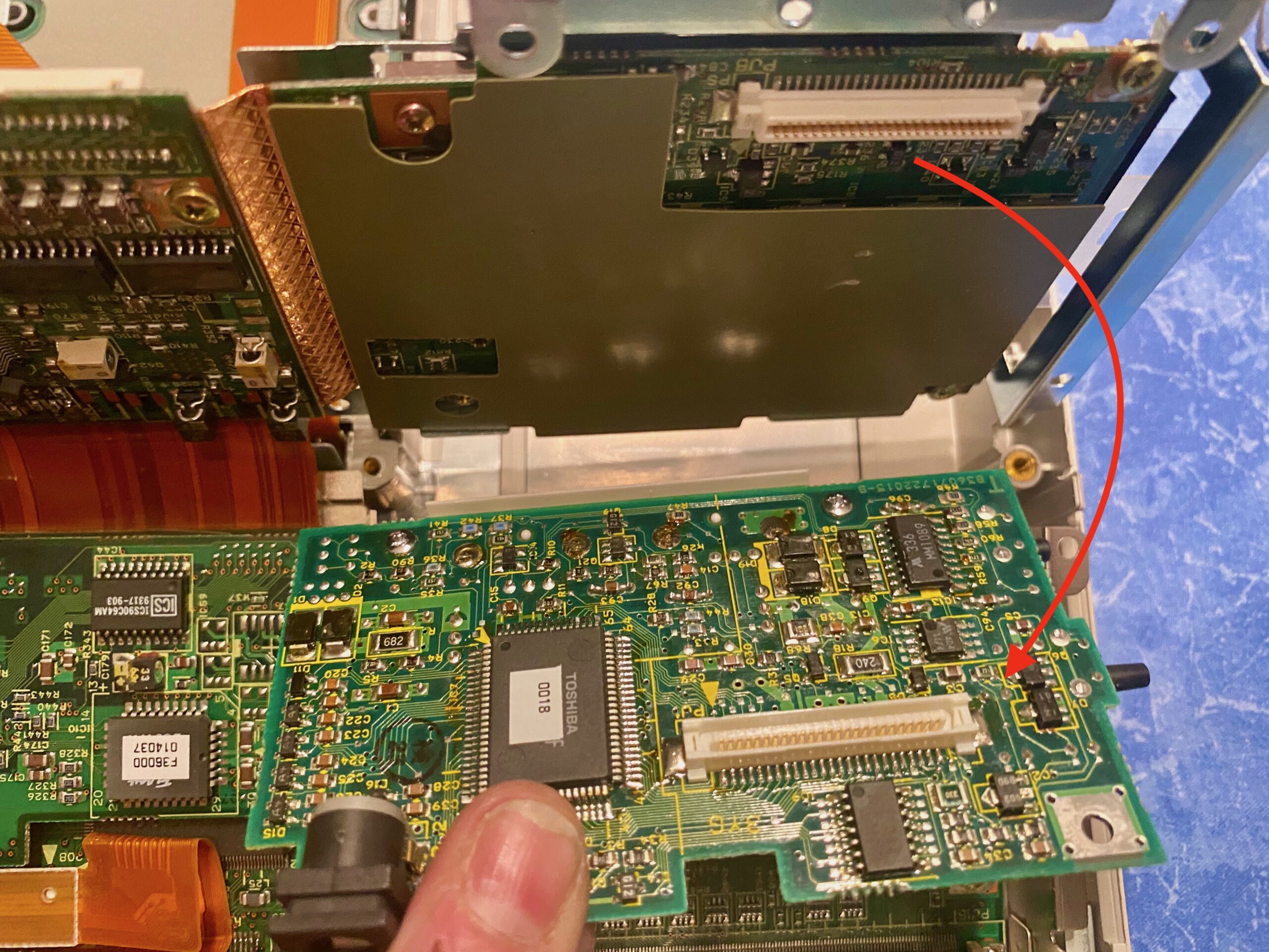
- 32. Luckily the PSU board can be pulled off without any more screws. It’s just plugged in to this white slot.
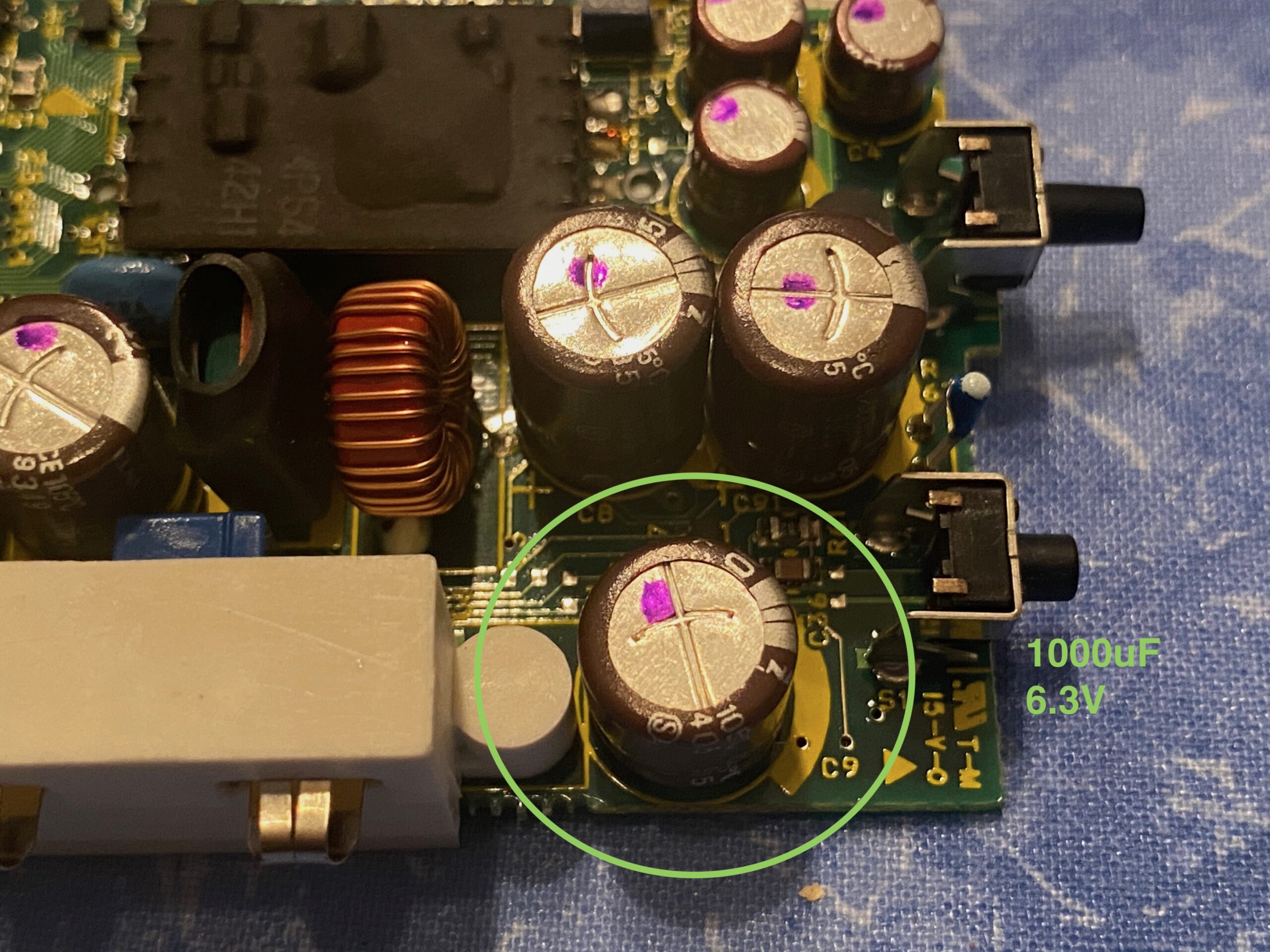
- 33. And here it is, the stinky capacitor. It doesn’t look blown out on top, but it’s leaking below.
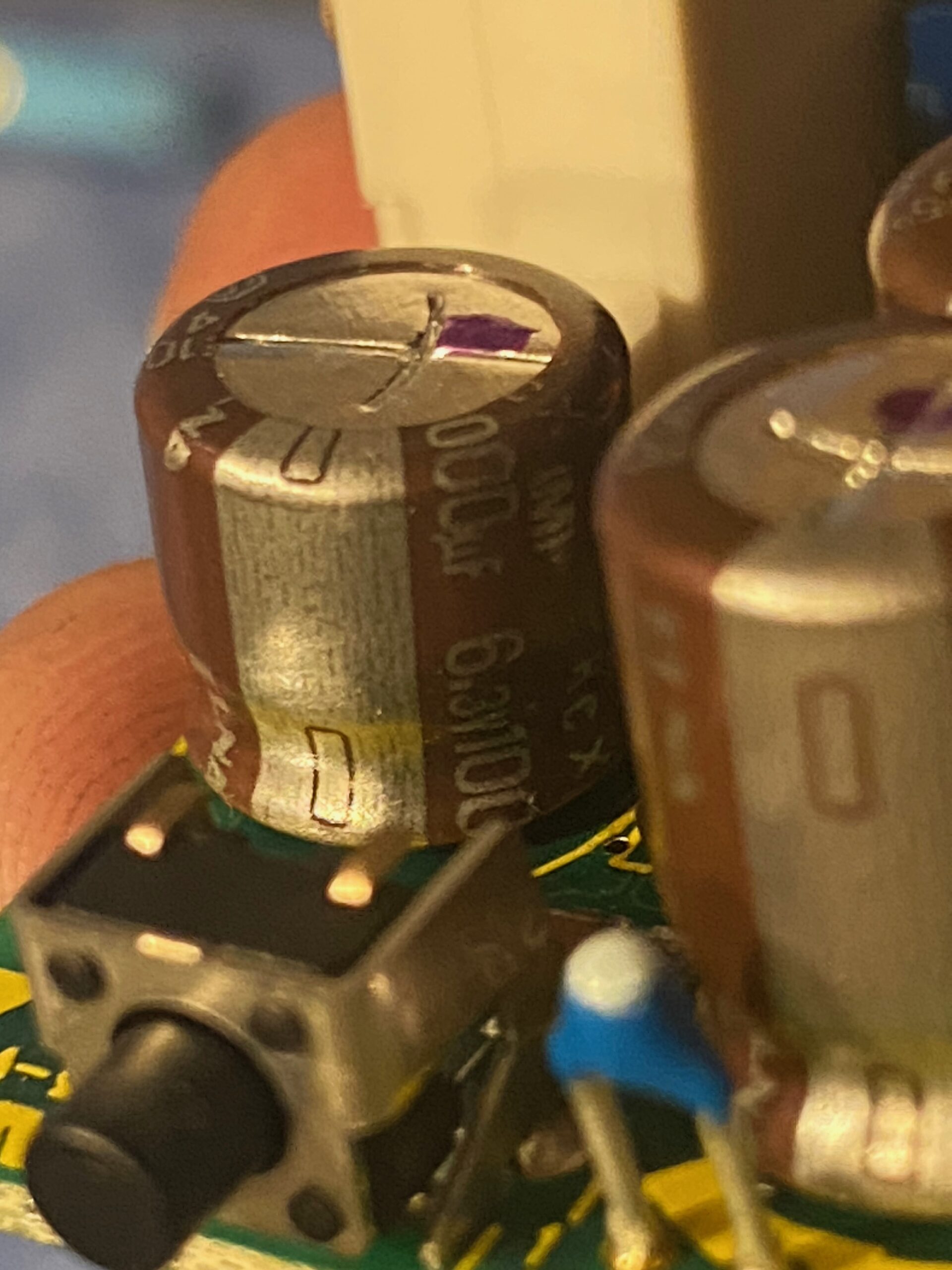
- It is a 1000uF capacitor with 6.3V.
Pay attention to it’s height! Most replacements are taller and won’t fit when putting the board back into place. - I didn’t have a 6.3V capacitor and replaced it with an 12V.
- What a mess!
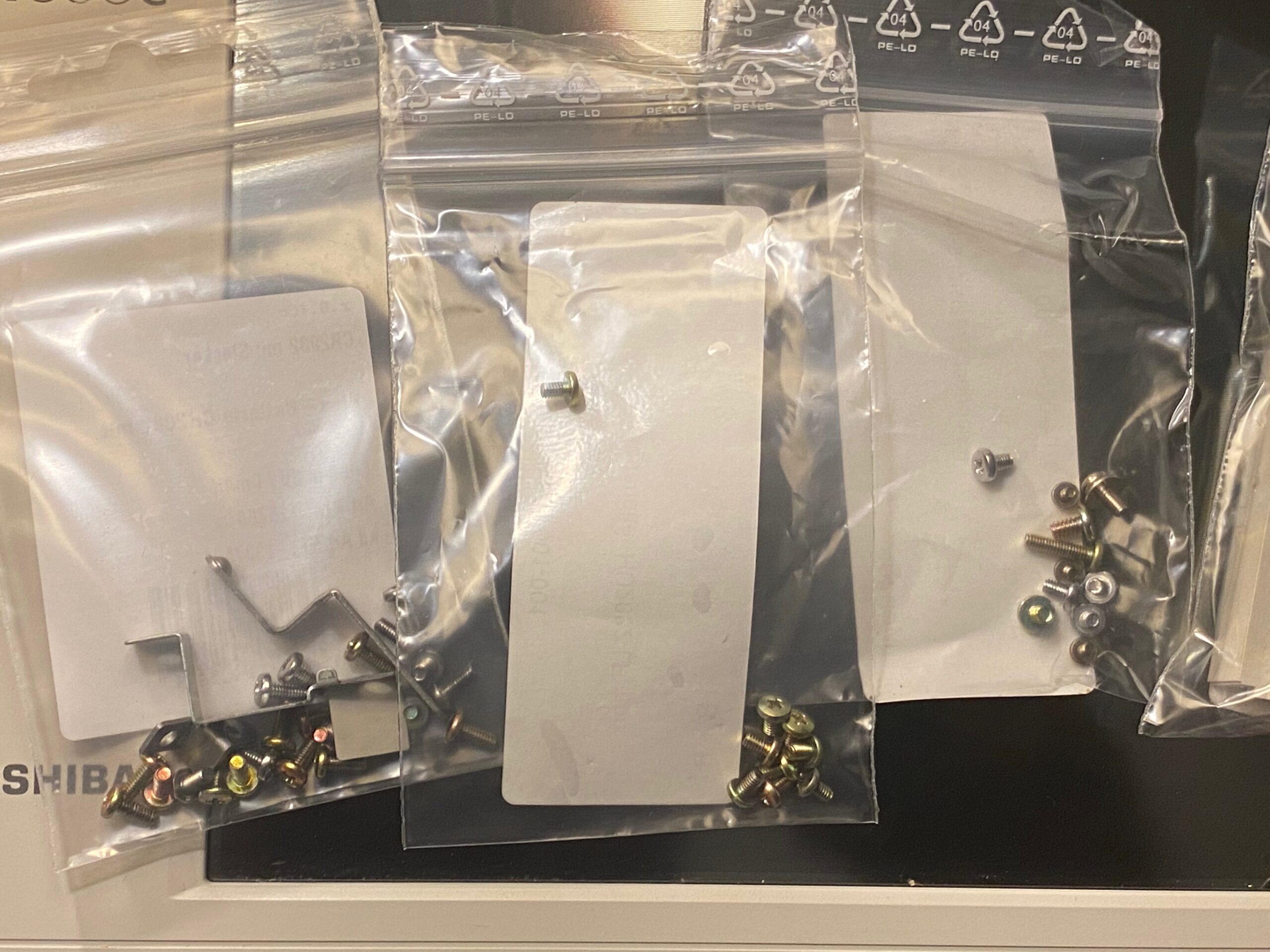
- That’s about 45 screws!
GOOD LUCK PUTTING IT BACK TOGETHER!